| M30 Ammunition Carrier | UM Kit #226 |
| Article by Stephen Brezinski; last updated 10 January 2016 | |
 |
|
| Modeling the Sherman Tank in 1/72nd Scale |
| M30 Ammunition Carrier | UM Kit #226 |
| Article by Stephen Brezinski; last updated 10 January 2016 | |
|
|
| This review covers a
construction review for the 1/72-scale US Army M30
ammunition carrier model kit for the M12 Gun Motor
carriers (GMC) kits in small scale, from the old
venerable ESCI company, and a new release from
UM. Along with the UM M12 kit, UM has this new kit
of the M30 ammunition carrier that accompanied and
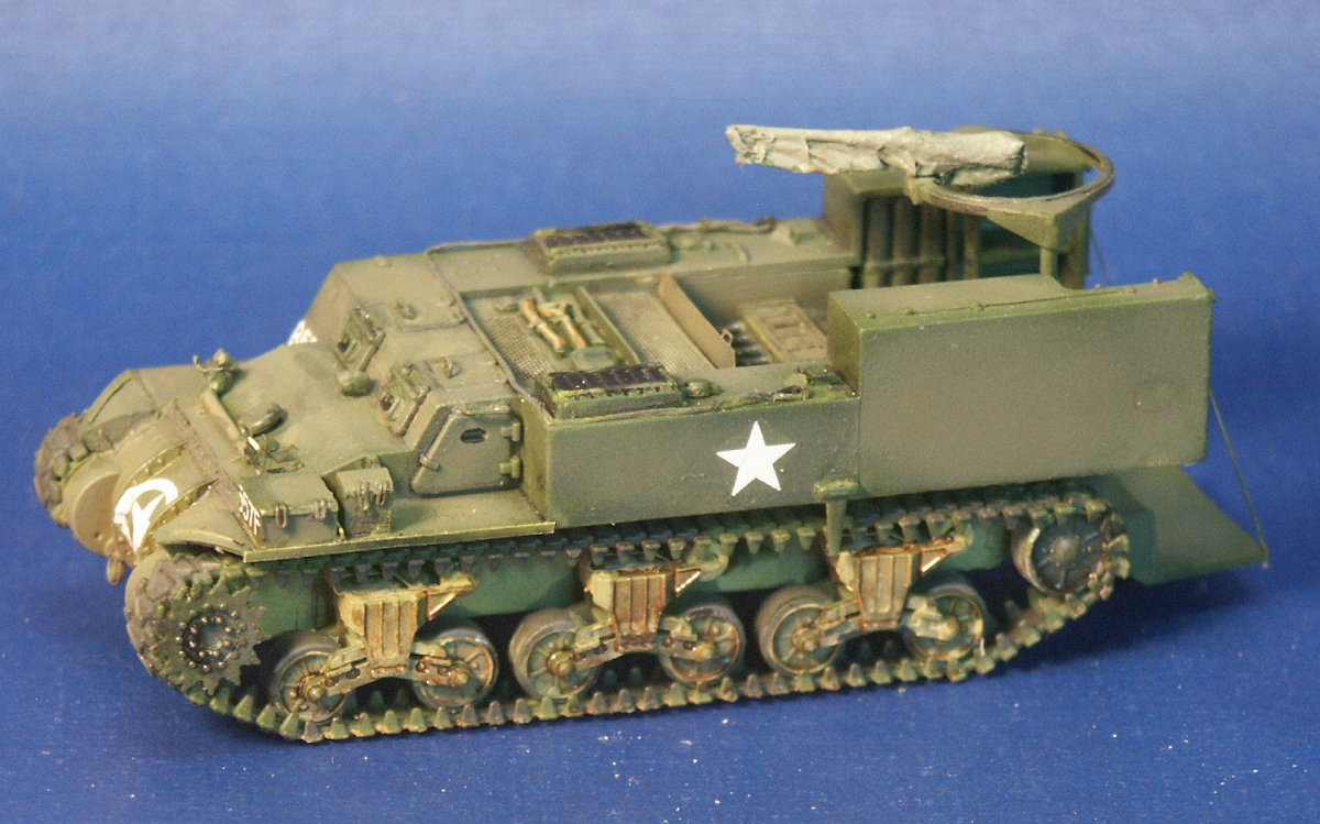
supported the M12. So much more can be discovered about a model kit from assembling it of course. For a look at the kits in the boxes please see here. For me, the process of building a model kit is as important as the outcome. I love seeing how a manufacturer has engineered the kit, how it assembles, and how I can make it better. I did not have a lot of good references on this vehicle, the best one is a construction and conversion article by Steve Zaloga in Military Modelling Volume 37, No.13 2007; unfortunately I did not get this article till after I competed my models. The UM M30 kit boxart shows what to me looks like a pretty accurate M30 and with a deployed M12 GMC in the background. The track appears to be the chevron pattern rubber block T48 track which is what is supplied in the model kit (and all UM Sherman based kits so far). The most common track I have seen in historical photos on the M30 is the flat block T41 or T51 track. All M12s and M30s were produced with the 3-part bolted final drive assembly cover. Near the headlights are what appear to be lifting rings on the side of the superstructure. I have seen these lifting rings on both the M12 and M30 in most, but not all, historical photos of the vehicles. Neither the UM kits nor the ESCI kit include these lifting rings.
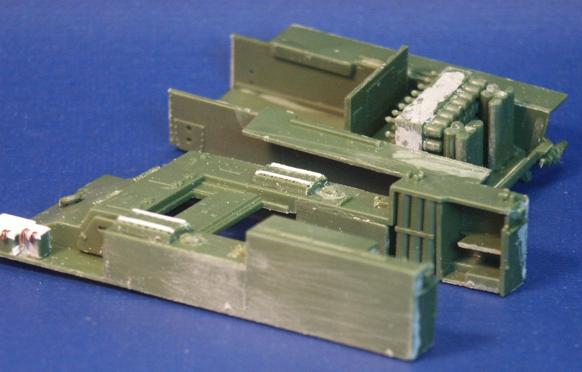
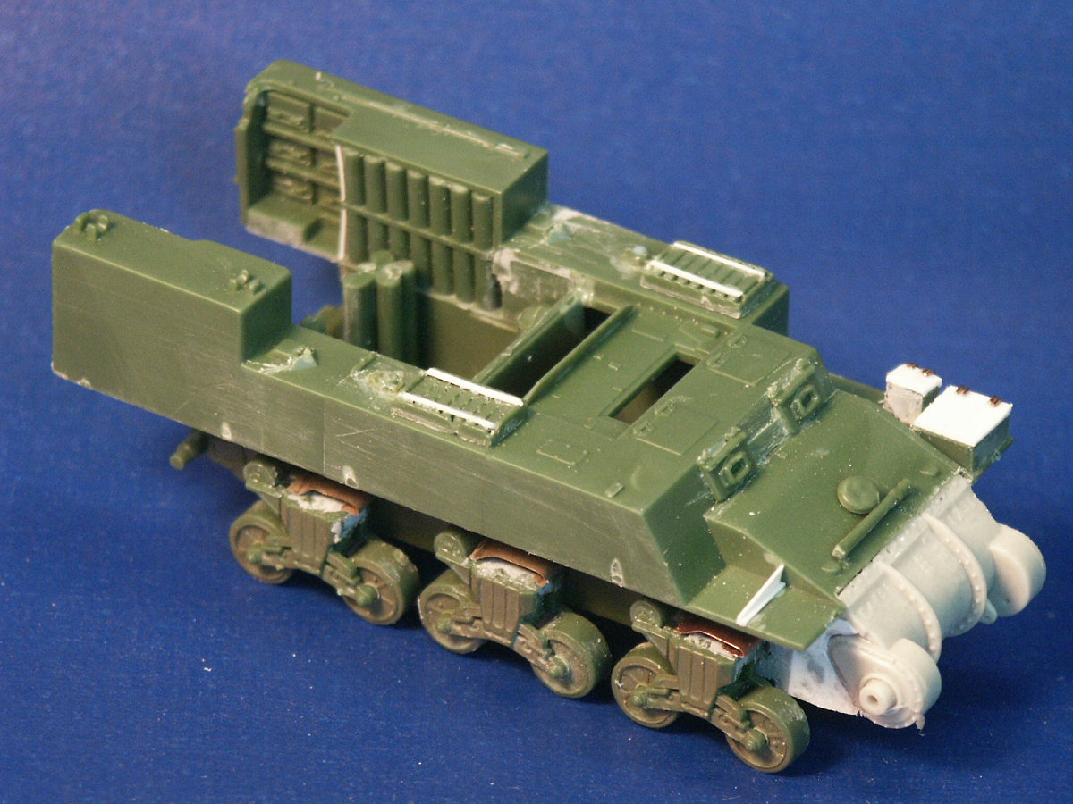
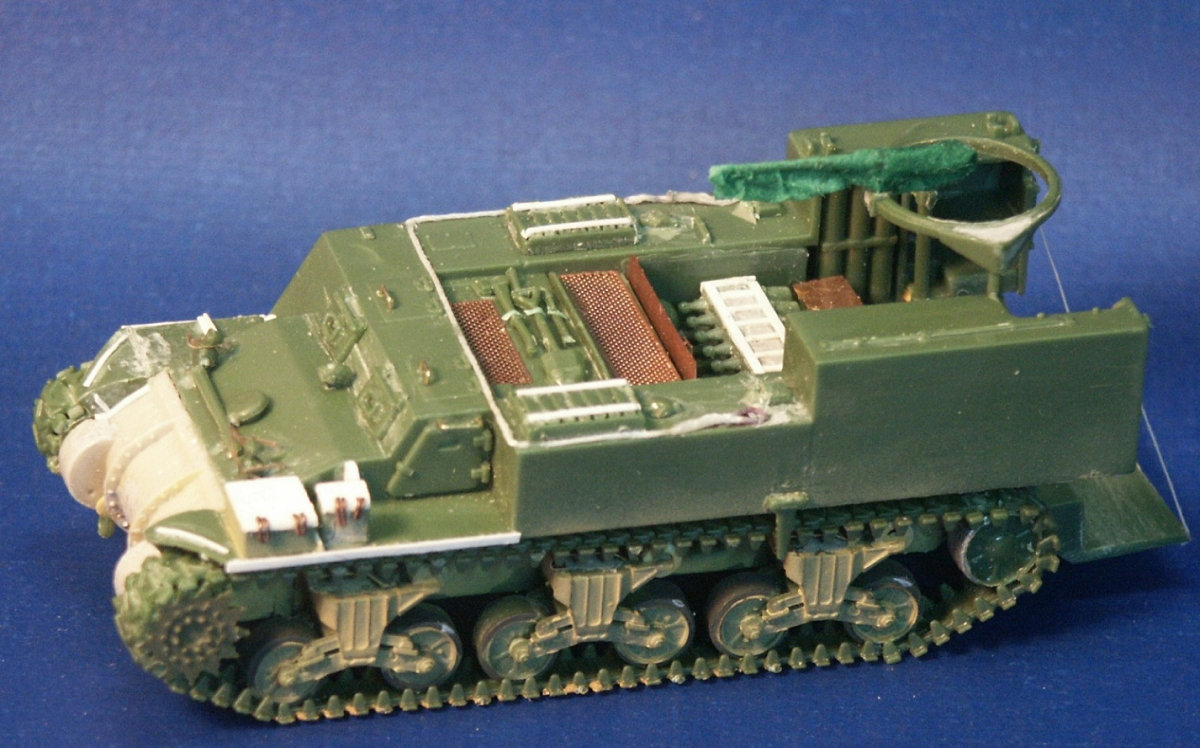
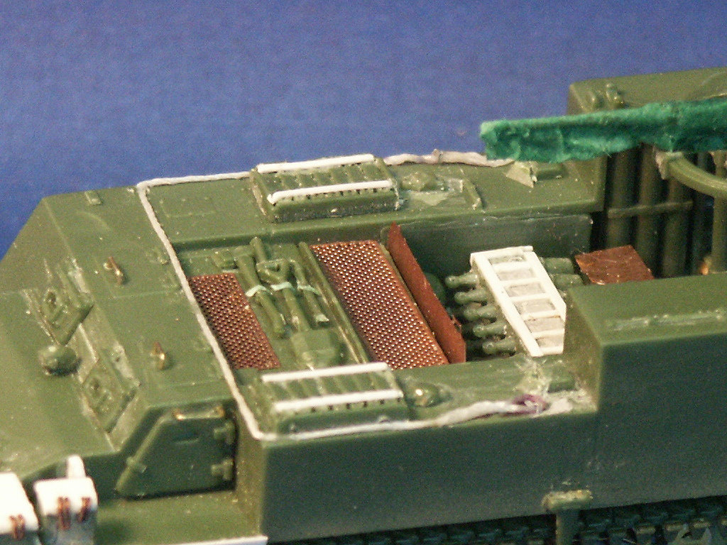
We see the forward part of the upper hull is the same as the M12 but the M30 rear section of the hull is redesigned for significantly more ammunition storage. Sitting on the deck of the lower M30 hull is a storage rack of 56 artillery shells (parts 2C). The long vertical tubes I suspect hold the cartridges and propellant. Good reference photos for this vehicle are uncommon, on the ones I have it show the ammunition tubes store horizontally.
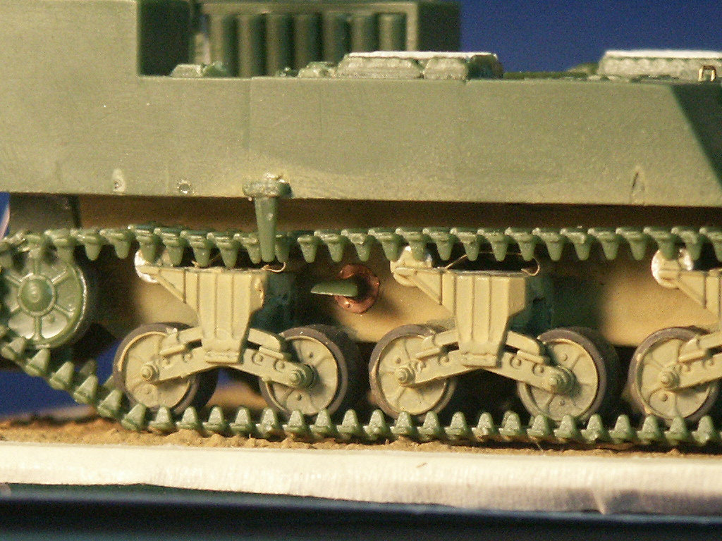
Using major surgery on the lower hull (parts-10B & 11B) the front parts for the final drive was cut off to prepare for a replacement final drive assembly. In the past I've assembled two of UMs final drive assemblies and I was not looking forward to building one again (see my reviews of the UM M12 and a UM M4A4 kit to see what I refer to). To the right is an extra resin 3-piece bolted final drive housing made by Wee Vehicles that I will mate onto the plastic kit. Mating this resin part to the plastic kit is easier than assembling another UM final drive (parts 15, 64, 65, 104 & 105).
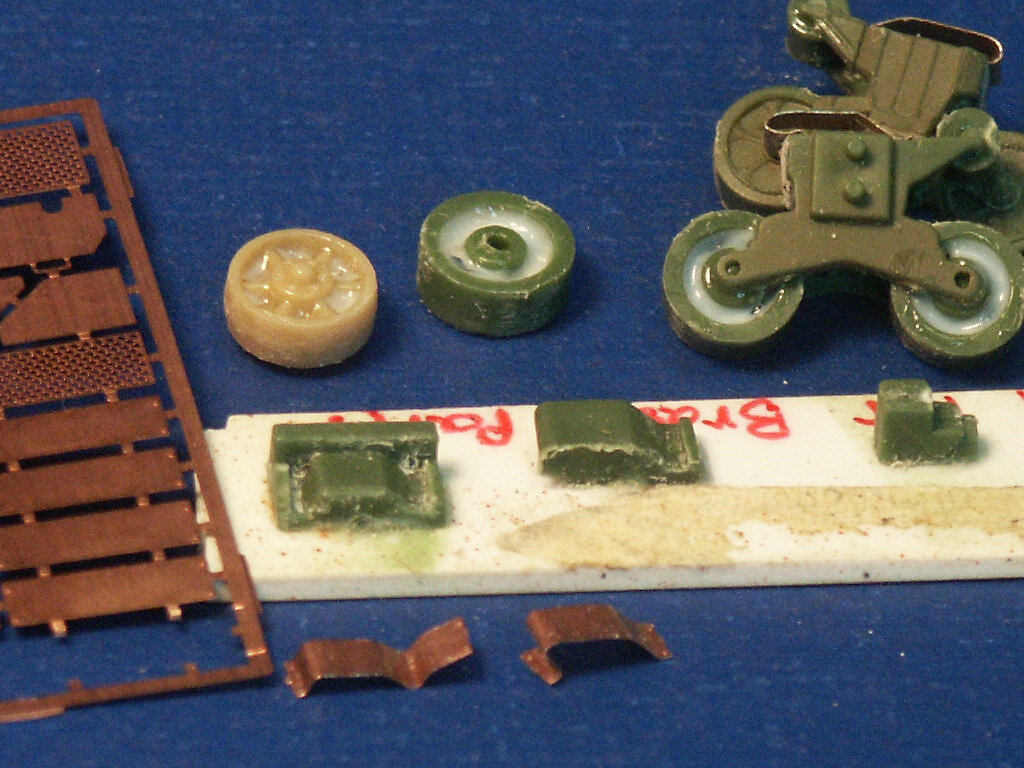
The back of UM's stamped type roadwheels (parts-5A) are hollow so considering that some contest judges like to look under the model, the hollow well was filled with white glue. Below are the forms included in the UM Sherman kits for bending the brass light brush guards (parts-8F) and the track skids into shape. At bottom are some etched brass skids bent into roughly the shape for mounting on the VVSS bogies (at upper right).
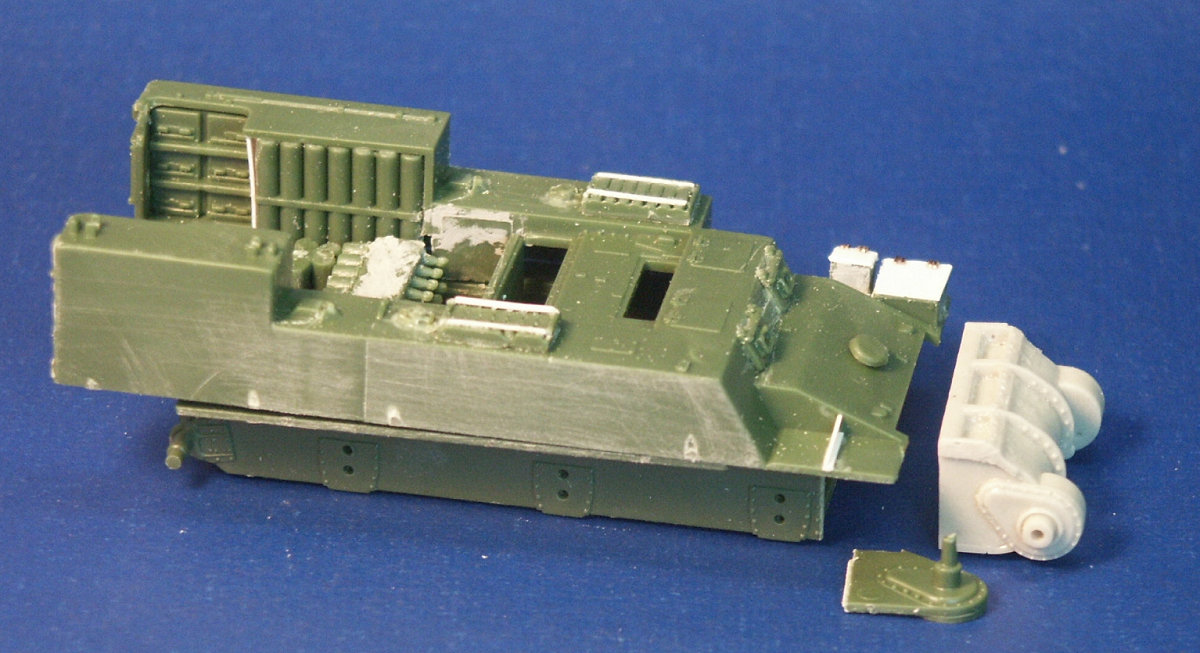
The Wee Vehicles resin final drive part has been glued on with super glue and a big gap supported with some blocks of styrene. Several of the suspension units had scratchbuilt return rollers instead of the kit parts-6A. The hull bottom is missing a few details but does have the escape hatch and is more accurate than the ESCI kit.
The hull largely assembled minus some of the small details, like the etched brass, which will be added after the rest of the wheels and the tracks are attached to the model. Molding the driver's hatches separate and open would have been a nice option.
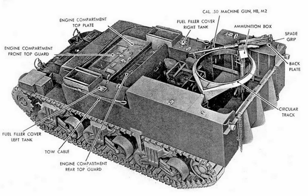
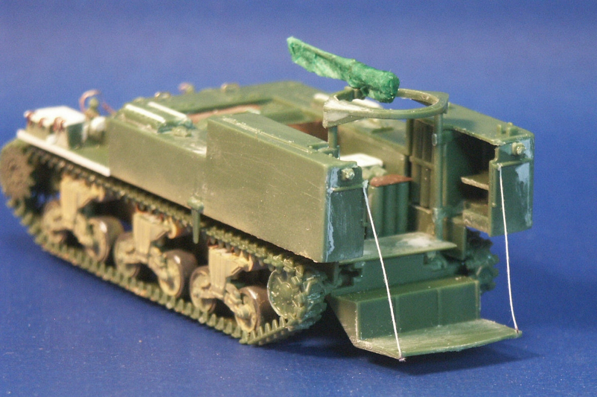
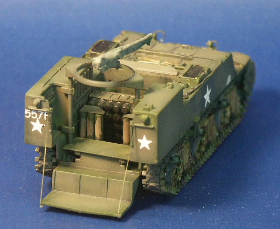
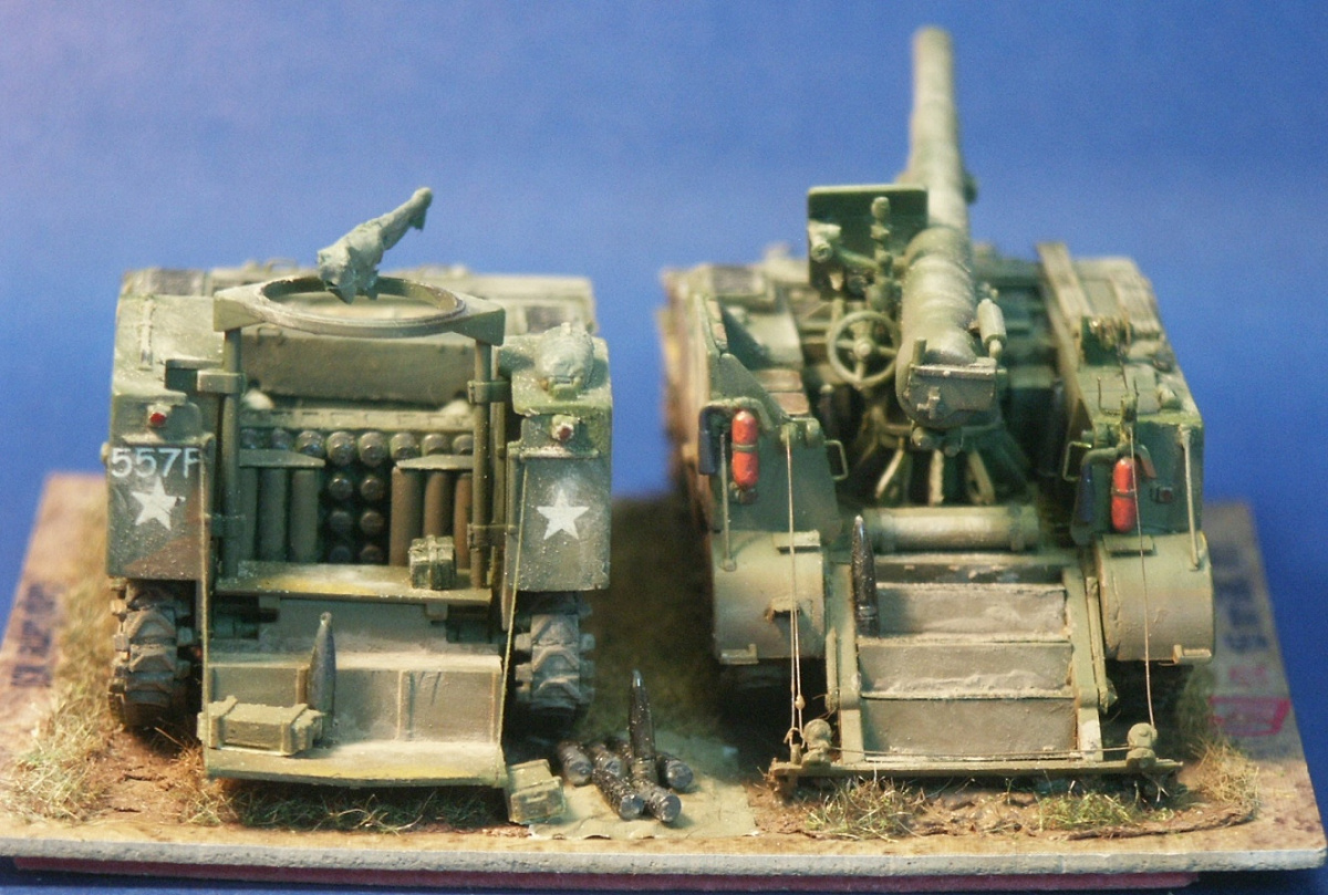
This excellent US Army photo is the best one I have seen for interior and exterior details. Starting from the rear: there are chains to hold the ramp in place when it is lowered but I see no winch system to lift it back up into traveling position like there is for the M12 ramp. The details of the machine gun mount are not great but can help us in detailing the UM AA weapon. The track appears to be the T41 or T51 type common to the M12 and M30. The two grouser storage boxes are empty.
The rear steps (part 8C) are held up by some thread to simulate the chain that actually supported the steps. In the ammunition compartment we can see the placement of the various etched brass parts (I think and hope I got them in the correct places).
Rather than detail the .50 caliber AA machine gun (parts 31B & 76B) I opted to cover it with a tarp simulated by tissue paper coated in white glue. This is the tissue paper used in gift wrapping, not the wimpy soft stuff for blowing our noses.
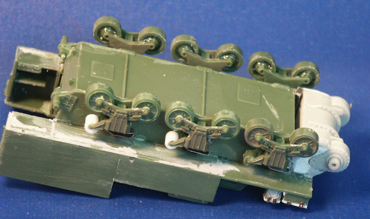
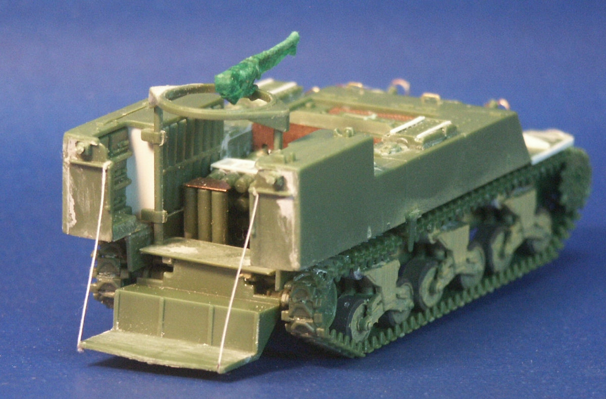
Since starting this model I could not comprehend where the engine exhausts were on the vehicle. On the M4 Sherman tanks the exhaust was directed out the rear of the engine compartment. With the rear gun compartment and fold down spade and steps of the M12 and M30, this was not feasible. Within the UM M12 and M30 kits on sprue H there were two parts that looked just like flared exhaust pipes. Finally, buried in Step-6 of the UM instructions I discovered directions to assemble exhausts coming out of the port and starboard sides of the lower hull using (parts 9F & 16H). There are no indicator markings on the lower hull sides to show where the exhaust outlet is exactly supposed to be, so we have to do it by eye, between the 2nd and 3rd VVSS bodies (see photo above). The long triangular, sword-like part (parts 7H) that hangs down and mounts on both of the upper hull sides (see Step 16 of the instructions). These parts are included in the UM and the ESCI M12 kits, and M30 kit, but at I assembled the kit I had no clue what purpose these little wedges serve. A good reference photo or two, and help from Rob Haelterman, showed that this part supported a rectangular steel brace that went from the part to the front of the last VVSS bogie assembly. This brace apparently helped absorb stress on the bogie when the big 155-mm gun fired. I find it strange that this brace was built into the M30 when the M30 could not mount a gun. UM's rendition of this part does not look long enough, it does not hang down far enough.
The UM .50-calibre AA machine gun (parts 31B, 76B, et al) is decent but could use some detailing. Rather than do the detailing I close to just cover it in a simulated tarp like for a vehicle in transit. The storage boxes on the portside mudguard have some lids made from styrene sheet and latches simulated from copper wire.
The engine intake screens, etched parts 1F and 3F, look more realistic than ESCI's approach of molding in the screen pattern, but be careful not to clog the tiny holes with glue and paint. The tow cable has been made from tea bag string coated in white glue to give it some stiffness and then the end was glued into a loop. The resulting tow cable and loop is in my opinion more realistic than the molded styrene cable and ends supplied in the ESCI M12 kit. With strips of styrene a metal frame has been simulated on the ammunition storage rack. Leather straps have been simulated on the shovel, axe and other tools with tape.
Skipping ahead after painting with olive green and olive drab acrylic paints and a dark wash in recesses. Like all my models using water slide decals, the decals were applied over a coat of clear glass acrylic floor polish. The star marking at the left side broke in two when being removed from the paper. Based on the kit marking guide I believe the vehicle number decals "557P" on the left rear and left front of the upper hull are too large in size.
The star decal on the nose was a little too large based on the historical photos and the kit markings guide and the decal curved up over the flanges and bolts of the 3-piece bolted differential housing making the setting solution absolutely needed. The setting solution softens the decal film and helps it nestle down around surface detail as it dries. These UM decals held up better than the elderly decals in my ESCI M12 kit.
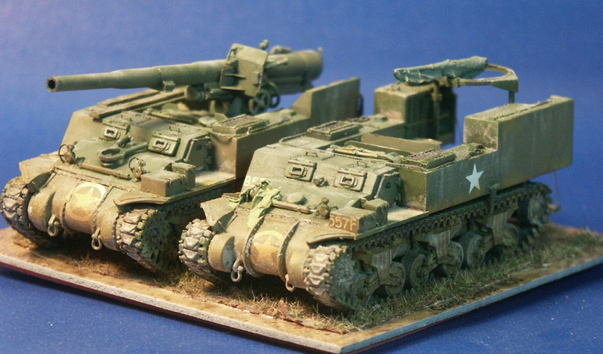
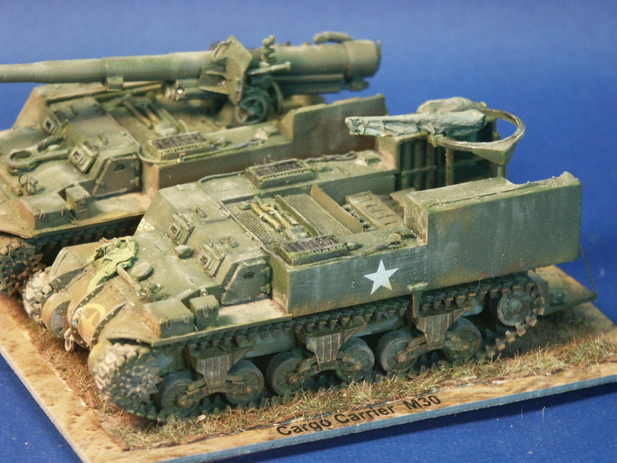
To the right of the UM M12 model, the UM M30 kit only comes with one marking option, for a US Army 557th Field Artillery Battalion vehicle serving in Germany in February of 1945. Notice how the vehicle number 557F appears too big for the storage box on the starboard fender. I find the resin replacement differential housing used on the M30 to look superior to the UM kit differential housing that comes with the kit which is seen here on the UM M12 kit at left.
Weathering was competed with a light mist of dark tan acrylic paint sprayed on, paint pigment powder in the crevasses, and Tamiya Weathering Master for highlighting and streaking the hull.
I think some good crew member figures would be very nice here, some of my favorites are from Milicast. Some ammunition bags would also be nice. This gun used bagged ammunition and was stored in the long tubes seen here standing upright in the rear of the M30. From one reference photo, the real life size white cloth propellant bags look about 50 to 60cm long and about 15cm wide. This is the only M30 kit I am aware of in 1/72-scale so there is not anything to fairly compare it with. I did know of Steve Zaloga's conversion of an ESCI 1/72-scale M12 into an M30 (Military Modelling magazine, Volume 37, No.13 2007) which required major surgery and scratchbuilding, but this is not a fair comparison. Overall, I am very pleased with the model; not as good a model as a Revell or Dragon plastic kit, but a good model. I am very happy that UM released this unusual and rare vehicle. References U.S. Self-Propelled Guns in Action, Armor Number 38, by Jim Mesko, Squadron/Signal Publications (1999) The Sherman Design & Development, Son of Sherman, Volume 1, softcover or hardcover book by The Ampersand Group Inc. (2013) Sherman Minutia website http://the.shadock.free.fr/sherman_minutia/index.html Tankograd Technical manual series 6030 about M12 and M40. U.S. WW II Heavy Self-Propelled Artillery M12, M40, M43, by Verlag Jochen Vollert, Tankograd Publishing (2014) Paperback. |
| Modeling the Sherman Tank in 1/72nd Scale |